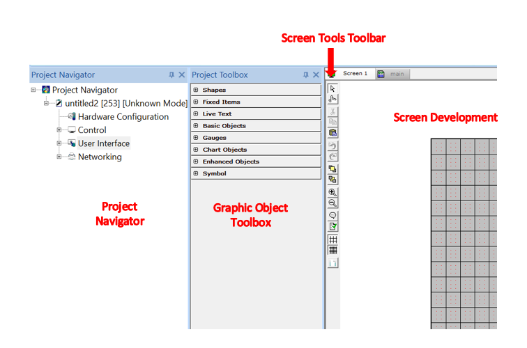
Screen Development
See also: User Interface
See also: Graphic Object Toolbox for Canvas Series
See also: Graphic Object Toolbox
Topic Menu
Note: Users may drop a program in the Logic Editing Area, however the dropping of program is restricted on Screen tab. The Screen tab has its own drop functionality which allows only graphic objects to be dropped.
Screen Development Workspace
A new screen must be added in order to open Screen Workspace:
To add New Screen: Home > View > Project Navigator > User Interface > Main Screen [Right-Click] > New Screen
One a Screen Workspace is created, the Graphic Object Toolbox will be available.
To add Objects: Home > View > Project Toolbox
Note: Ensure the proper workspace is showing Screen and not Main.
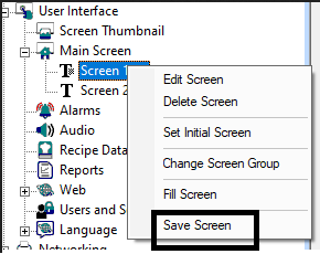
Save Screen
Right click on any screen that needs to be saved, an option for “Save Screen” will be available. Selecting “Save Screen” displays window for saving the screen in desired location.
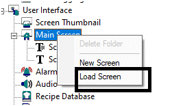
Load Screen
Right click on Main Screen option of User Interface, displays an option for “Load Screen”. Selecting “Load Screen” option displays window for selecting any saved screen that can be loaded.
Return to the Top: Screen Development
Screen Tools Toolbar
|
|
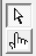
Selector: The Selector arrow is the default tool that appears on-screen unless another operation is active. The Selector arrow selects, moves and re-sizes objects.
Operator Simulator: Upon pressing this button, the Operator Simulator icon appears on-screen. To animate objects including switches, indicators, and meters, drag the Operator Simulator icon to desired object and left-click the mouse. In some instances, each left-click of the mouse changes the state of the object. In other instances, each left click steps through a series of static bitmaps |
|
|
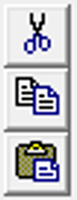
Cut/Copy/Paste: These functions allow objects or groups to be cut, copied or pasted to the current or newly selected screen. |

|
Previous Screen: Pressing this button jumps to the screen previously viewed. This is not always the next lower screen number. Next Screen: Pressing this button jumps to the next screen.
|
|
|
To Front: If multiple objects are overlapped, this function causes the selected object to be drawn last or on top of the other objects.
To Back: If multiple objects are overlapped, this function causes the selected object to be drawn first or covered by the other objects. |
|
|
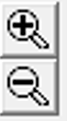
Zoom In : To magnify the representation of the OCS unit on-screen, click the Zoom In (+) button. Zoom Out :Continue to click this button until the desired size is reached. Use the Zoom Out (-) button to do the opposite. |
|
|
View/Edit Screen Comments: This function is used to store notes and questions with the current screen which are used strictly for the use of the programmer. If comments exist for the current display screen, the Comments button animates and flashes as an indicator to the user. Error Check: Checks screens for various warnings and errors. |
|
|
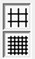
Snap to Primary Grid: When pressed, this button causes inserted or moved objects to snap to the primary grid lines. This button does not effect the Static Text object or Drawing Primitives. Snap to Secondary Grid: When pressed, this button causes inserted or moved Static Text objects or Drawing Primitives to snap to the secondary grid lines. If the Snap to Primary Grid button is disabled, this button will also cause the other object types to snap to the secondary grid. |
|
|
Set Background : Applies the selected color from color picker as solid background color. |


Return to the Top: Screen Development
Display Screens Overview
A screen is the display area that provides a background color and contains a collection of user-configured objects. Up to 250 of these screens can be stored in the Micro OCS (excluding the X5) series, while up to 1023 of these screens can be stored in all the XL series controllers and the X5 controller. Since one screen is presented at a time, the OCS contains mechanisms that allow the operator to change the current display screen. These mechanisms allow switching screens from the front panel, ladder program or network. In addition, three priority levels of screen control exist that allows the current screen to be 'interrupted' by either the system menu or an alarm screen. This section defines screen numbering, attributes and methods available to change screens.
Initial Screen
Each user-created screen is assigned a screen number. This number is used to identify the screen both in the editing environment and in the run-time environment (indirect screen references). Screen numbers begin at 1 and go to 250 for the Micro OCS series (excluding the X5), or from 1 to 1023 for the XL series and the X5. The first screen that is displayed at power-up and at any non-RUN to RUN mode change is referred to as the Initial Screen. The Initial Screen is also the return screen when recovering from an Undefined or Invalid screen (Esc key). While the default Initial screen number is 1, the Initial screen number is modifiable by the editor through the Screens/Set Initial Screen menu or on the right-click display menu.
Screen Properties
Each screen has two configurable properties: background color and comments. The background color, which defaults to white, may be set to a different color through the Screens/Set background… menu or through the right-click display menu. Individual object foreground and background colors may also be modified to match this color scheme. Each screen may also contain a ’hidden’ comment section, which the designer may use for design comments or documentation. The comment editor is accessed through Screens/Comments… menu or through a button on the tools toolbar.
Screen Priority Levels
Screen display control is prioritized at three levels: USER, ALARM and SYSTEM MENU. The SYSTEM MENU has highest priority in that it can always interrupt the current screen when the System keys are pressed. The next priority level is that of the ALARM screen. An ALARM screen can interrupt the current USER screen when activated by the Force Screen function of the Switch Screen coil from ladder code. If neither the SYSTEM MENU nor ALARM screen is active, the current USER screen will be displayed.
The priority level is actually controlled by 3 system controller registers (%SR1-3). %SR1 controls the lowest priority level or USER screen and should always contain a screen number between 1 and 250 for the Micro OCS series (excluding the X5), or between 1 and 1023 for the XL series including the X5. %SR1 is modified when the Screen Jump object or the Switch Screen ladder coil (Switch Screen) is used to change the USER screen. %SR1 is initialized with the Initial screen number at power-up and non-RUN to RUN mode changes. %SR2 controls a higher priority or ALARM screen and should contain a screen number of 0 if no alarms are active or a number between 1 and 250 for the Micro OCS series (excluding the X5), or between 1 and 1023 for the XL series, including the X5. %SR2 is modified when the Switch Screen ladder coil (Force Screen) is used to display an ALARM screen.
The ALARM screen is removed once the associated Switch Screen ladder coil no longer passes power (%SR2 returns to zero). %SR3 controls the highest priority or SYSTEM MENU screen and should contain a screen number of 0 if no System Screens are active. A number above 0 will indicate a system screen being displayed. %SR3 is modified when the front panel system’ keys are used to display the system menu. The SYSTEM MENU is removed once the operator presses the ESC key to exit (%SR3 returns to zero). See System Registers for more information on System Screen values.
Generally, registers %SR1-3 are not accessed directly by the operator but may be used to monitor the current display level. An example is when the ladder application may be used to block screens (power Switch Screen coil if %SR1 is equal to certain screen numbers) to create a password privilege scheme.
Screen Control with Screen Jump Object
See also: Screen Jump Object for Canvas
A Screen Jump object that may be tied to a specific key or I/O point to activate a screen switch (jump). This provides a more structured or directed way of navigating through screens. Screen Jump objects can be displayed on a screen as individual objects or grouped to create ’virtual’ menus. Virtual menus allow the operator to scroll a cursor through a list of screens and then press Edit/Enter to jump to the selected screen. A Screen Jump object can be configured with an absolute screen number or receive a screen number indirectly through an OCS register at run-time allowing program dependent screen navigation.
When a screen is created with the editor, there is NO specific indication on whether that screen will be displayed under USER or ALARM screen priority level. The priority level is determined at run-time through indirect control of the %SR(1-3) system registers. Normally, all objects will function on any particular screen regardless of the screen priority level (USER or ALARM). However, the Screen Jump object is an exception in that it will only effect a screen change if the current screen priority level is at USER. For more information on the Screen Jump object, refer to the Screen Jump object in the object reference.
Screen Jump Queue
Included in the screen jump mechanism is a screen jump queue. The Screen Jump object can optionally save its associated screen’s number to the queue before effecting the jump. When the operator is finished with the information on the new screen, the front panel ESC key or a Touch Screen Jump that is configured to emulate the ESC key can then be used to return to the screen effecting the jump. This allows operators to ’back out’ of help screens, action warning screens, or a sequence of ’virtual’ menus by pressing the ESC key for each level.
Up to 16 jump levels can be queued with the ’last’ 16 jumps being stored.
Once all of the screen jumps are ’popped’ from the queue, the ESC key will not effect the last remaining screen. The ESC key only restores previous screens if the current privilege level is at USER. Pressing the ESC key when the current privilege level is at ALARM will NOT cause a screen change or effect the screen jump queue. Note that the queue is automatically flushed if the USER screen (%SR1) is changed remotely (ladder Switch Screen coil or network).
Screen Cursor (Run-Time) ( Non-touch Controllers Only)
*Non-touch units include X2, XLE, and XLEe.
**Touch Units include all XL series, Prime Series, and Micro OCS series controllers.
Screens that contain (Text) Data objects that are editable <or> Binary objects whose keypress source is set to ’cursor selectable’ will display an object cursor. This cursor will be visible as a dashed line around the bounding rectangle of the currently selected object. On the initial display of a screen, the upper-leftmost object selectable will be selected. The operator, with the use of the arrow keys, can select a different selectable object. Once an object is selected, an additional keystroke will be required to enter the object’s editor. For (Text) Data objects, an alpha-numeric key will invoke the selected objects editor. For Binary objects, the Edit/Enter key will generate the binary input action.
When selecting objects, the direction of the arrow key pressed defines the direction of cursor movement. The non-touch controllers will attempt to select the closest object in that direction. When determining the closest object, the only objects considered will be those whose center falls within a plus-or-minus 45degree angle from the center of the currently selected object (in the direction of the arrow key). This method allows a selection path to any object regardless of its position on the screen; however, it is strongly recommended that selectable objects always be perpendicularly placed to reduce operator confusion. Note that since an object’s relative location is based on the object’s center, the user should also use consistent object sizes when laying out the selectable objects.
When selecting objects that are fully or partially covered, that object will be placed on top of the other objects as long as that object is selected. If no object falls within the direction of the arrow key, no cursor change will occur. Screens that contain NO selectable objects will not display a screen cursor.
Using Screen Number System Registers
See Also: System Register Tables
The controllers contain system registers that allow the user, alarm and system screen numbers to be read and/or written. The following is a definition of the three types of screens, listed from highest priority to lowest priority:
-
System Screens - These are the predefined screens that make-up the system menu. System screen one is viewed by pressing the system key on the controller. Additional system screens can be viewed by navigating the various menus that make-up the system menu. Any system screen can also be displayed by writing a screen number to the system screen system register. System screens are shown even if alarm or the user screens are active.
-
Alarm Screen - These screens are programmer defined screens that are forced to display using a %D coil in ladder logic. The alarm screen system register can be read to determine which screen is being forced as an alarm. Writing to the alarm screen system register does not affect operations because the ladder processor calculates and writes the alarm screen number each scan. For text-based controllers, these screens can be marked as Alarm when creating the screens. However, screens that are not marked as Alarm but are forced using %D coils are considered alarm screens in this context.
-
User Screen - If a system screen and alarm screen is not displayed, a user screen is displayed. If more than one user screen exist (programmer not defined as Alarm), the operator can switch between screens using the UP and DOWN keys on the controller on text-based controllers only. Reading the user screen system register allows the ladder program to monitor the operators movement through the screens as they scroll using the UP and DOWN keys . Writing to the user screen system register allows the ladder program to directly control the screen being displayed.
In order to change the graphics screens to a particular group, right on screen (1) & select option for the Change Screen Group in the project navigator toolbox as shown below :
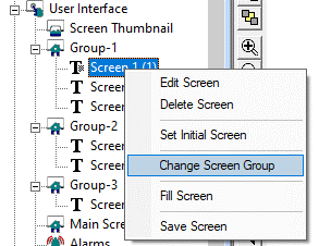
The following window will be displayed:
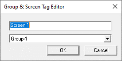
![]()
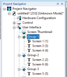
User can choose already created group from the drop down and the screen will be assigned to the chosen group. After assigning screens to groups, the same can be viewed from Project Navigator.
Return to the Top: Screen Development
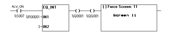
Display Coil
When a coil is used with a %D register it becomes a screen display coil. This allows ladder to easily control the screen number being shown on the display. When a coil is used as a screen display coil there are two options Force Screen and Switch Screen.
-
Force Screen - This displays a screen as long as the coil is active. This will override any other user screen being displayed. If more than one force screen is active at one time, the one that appears last in the ladder program is the one that is displayed. When a screen is being forced, its screen number can be read from %SR2, the alarm screen number.
-
Switch Screen - This allows the ladder program to switch the operator to a screen, but does not force this screen to remain active. The operator may choose to switch screen after the screen switch using various navigation methods (For example - menus, screen jumps, scrolling). Only one switch screen coil should be active at one time. If a switch screen is active and another one becomes active it will have no affect, however writing to %SR1 will change the screen while the switch screen is active.
Note: Power does not flow through the display coil. See Power Flow through the Element
Create a Display Coil
To create a display screen start with a coil:

Enter %D, then the screen number or press the "Screen >" button to see the screen picker.
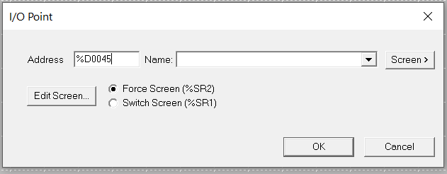
Select either Force Screen or Switch Screen and then press OK.
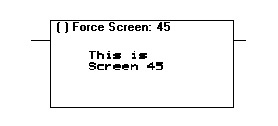
The coil will now expand to show a thumbnail of the screen if available.
Power Flow through the Element
Power does not flow through the Display Screen coil. The Display Screen Coil must be the last (right-most) element on the rung. In order to active multiple output coils on the same rung, the Display coil %D must be the last coil on the rung.
Return to the Top: Screen Development
Keyboard Shortcuts
Object sizing – applicable to both legacy and enhanced graphics objects
"Ctrl + Right Arrow key" will increase width of the object from both left and right side.
"Ctrl + Left arrow key" will decrease width of the object from both left and right side.
"Ctrl + Up Arrow key" will increase height of the object from both top and bottom side.
"Ctrl + Down arrow key" will decrease height of the object from both top and bottom side.
Object rotation - applicable to enhanced graphics objects only.
"Alt + Left Arrow Key" and "Alt + Right Arrow Key" – to rotate object clockwise or anti-clockwise respectively.